DME_Design of Machine Elements_Keys and Couplings
Keys
A key can be defined as a machine element which is used to
connect the transmission shaft to rotating machine elements like pulleys,
gears, sprockets or flywheels. A keyed joint consisting of shaft, hub and key.
There are two basic
functions of the key.
i)
The primary function of the key is to transmit
the torque from the shaft to the hub of the mating element and vice versa.
ii)
The second function of the key is to prevent
relative rotational motion between the shaft and the joined machine element
like gear or pulley. In most of the cases, the key also prevents axial motion
between two elements, except in case of feather key or splined connection.
There are different ways to classify key the keys. Some of
them are as follow:
- · Saddle key and sunk key
- · Square key and flat key
- · Taper key and parallel key
- · Key with and without Gib-head
The selection of the type of key for a given application
depends upon the following factor:
- · Power to be transmitted
- · Tightness of fit
- · Stability of connections
- · cost
SADDLE KEYS:
A saddle key is a key which fits in the keyway of the hub
only. In this case there ,there is no keyway on the shaft. There are two types
of saddle keys- 1. hollow saddle and 2. flat saddle.
A hollow saddle key has a concave surface at the bottom to
match the circular surface of the shaft.
A flat saddle key has a flat surface at the bottom and it
sits on the flat surface machined on the shaft. In both types of saddle keys, friction
between the shaft, key and hub prevents relative motion between the shaft and
hub.
- · Therefore, saddle keys are suitable for light duty or low power transmission as compared with sunk keys.
- · The power is transmitted by means of friction.
- · Flat saddle key is slightly superior to hollow saddle key as far as power transmitting capacity in concerned.

a) Hollow saddle key b) Flat saddle key
SUNK KEYS:
A sunk key is a key in which half the thickness of the key
fits into the keyway on the shaft and the remaining half in the keyway on the
hub. The standard form of key may be either of rectangular or square
cross-section. The power is transmitted due to shear resistance of the key. The
relative motion between the shaft and the hub is prevented by the shear
resistance of the key. Therefore sunk key is suitable for heavy duty
application.
- · The industrial practice is to use a square key with sides equal to one-quarter of the shaft diameter and length at least 1.5 times the shaft diameter.
- · The taper key is uniform in width but tapered in height. The standard taper is 1 in 100. The bottom surface of the key is straight and the top surface is given a taper.

Gib-head Taper Key
Feather Key:
A feather key is a parallel key which is fixed either to the
shaft or to the hub and which permits relative axial movement between them. The
feather key is a particular type of sunk key with uniform width and height.
There are number of methods to fix the key to the shaft or hub. Feather key
which is fixed to the shaft by means of two cap screws, having
countersunk-heads. There is a clearance fit between the key and the key-way in
the hub. Therefore, the hub is free to slide over the key. At same time, there
is no relative rotational movement between the shaft and the hub.
i)
The feather key transmits the torque and at the
same time permits some axial movement of the hub.
ii)
Feather keys are used where the parts mounted on
the shaft are required to slide along the shaft such as clutches or gear
shifting devices. It is an alternative to spline connection.

Fig: Feather Key
Woodruff Key:
A woodruff key is a sunk key in the form of an almost
semi-circular disk of uniform thickness. The key-way in the shaft is in the form
of a semi-circular recess with the same curvature as that of the key. The
bottom portion of the woodruff key fits into the circular key-way in the shaft.
The key-way in the hub is made in the usual manner. The projecting part of
woodruff key fits in the key-way in the hub. once placed in position, the
woodruff key tilts and aligns itself on the shaft. The advantage of woodruff
key are as follows:
i)
The woodruff key can be used in taper shaft.
ii)
The extra depth of the key in the shaft prevents
its tendency to slip over the shaft.
Woodruff keys are used on tapered shafts in machine tools
and automobiles.

Design of square and flat keys:
Although there are many types of keys, only square and flat
keys are extensively used in practice. A square key is a particular type of
flat key, in which the height is equal to the width of the cross-section.
Therefore , for purpose of analysis, a flat key is considered.
The force acting on
a flat key, with width as b and height as h are shown in figure.


The design of square or flat key is based on
two criteria, iz, failure due to shear stress and failure due to compressive
stress. The shear failure will occur in the plane AB . It is illustrated in the figure. The shear
stress τ
in the plane AB is given by
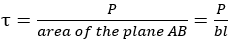
Where, b=
width of key (mm) and l= length of key(mm)

Fig: Failure of
key: a) Shear failure b) Crushing failure.
putting the value of P.
the
failure due to compressive stress will occur on surface AC or DB. The crushing
area between shaft and key is shown in figure.
It
is assumed that, AC=BD=h/2 where
h=height of key(mm)
The
compressive stress σc in the key is given by,

Therefore, compressive
stress induced in a square key due to the transmitted torque is twice the shear
stress.
Problem:
It is required to design a square key for fixing a gear on a shaft of 25 mm
diameter. The shaft is transmitting 15 kW power at 720 rpm to the gear. The key
is made of steel 50C4 (Syt = 460 N/mm2) and the factor of safety is 3. For key
material, the yield strength in compression can be assumed to be equal to the
yield strength in tension. Determine the dimensions of the key.
DESIGN OF KENNEDY KEY:
The Kennedy key
consists of two square keys as shown in Fig. 9.24. In this case, the hub is
bored off the centre and the two keys force the hub and the shaft to a
concentric position. Kennedy key is used for heavy duty applications. The
analysis of the Kennedy key is similar to that of the flat key.

Fig: Kennedy Key
It
is based on two criteria, viz., failure due to shear stress and failure due to
compressive stress. The forces acting on one of the two Kennedy keys are shown
in Figure. Since there are two keys, the torque transmitted by each key is one
half of the total torque. The two equal and opposite forces are due to the
transmitted torque. The exact location of the force is unknown. It is assumed
to act tangential to the shaft diameter.
COUPLINGS:
A coupling can be defined
as a mechanical device that permanently joins two rotating shafts to each
other. The most common application of coupling is joining of shafts of two
separately built or purchased units so that a new machine can be formed. For
example, a coupling is used to join the output shaft of an engine to the input
shaft of a hydraulic pump to raise water from well. A coupling is used to join
the output shaft of an electric motor to the input shaft of a gearbox in
machine tools. A coupling is also used to join the output shaft of an electric
motor to the input shaft of a compressor. There is a basic difference between a
coupling and a clutch. Coupling is a permanent connection, while the clutch can
connect or disconnect two shafts at the will of the operator. The shafts to be
connected by the coupling may have collinear axes, intersecting axes or
parallel axes with a small distance in between. Oldham coupling is used to
connect two parallel shafts when they are at a small distance apart. Hooke’s
coupling is used to connect two shafts having intersecting axes. When the axes
are collinear or in the same line, rigid or flexible couplings are used. While
the flexible coupling is capable of tolerating a small amount of misalignment
between the shafts, there is no such provision in rigid coupling. The
discussion in this chapter is restricted to rigid and flexible couplings. Oldham
and Hooke’s couplings are covered in more detail in textbooks on Theory of
Machines.
The difference between
rigid and flexible couplings is as follows:
(i)
A rigid coupling cannot tolerate misalignment
between the axes of the shafts. It can be used only when there is precise
alignment between two shafts. On the other hand, the flexible coupling, due to
provision of flexible elements like bush or disk, can tolerate 0.5° of angular
misalignment and 5 mm of axial displacement between the shafts.
(ii)
The
flexible elements provided in the flexible coupling absorb shocks and vibrations.
There is no such provision in rigid coupling. It can be used only where the
motion is free from shocks and vibrations.
(iii)
Rigid
coupling is simple and inexpensive. Flexible coupling is comparatively costlier
due to additional parts
Shaft coupling design
Procedure/Numerical
Shaft Coupling Design: Theory Questions
and answers and Numerical problems
Shaft
coupling design article containing design procedure and numerical problems of
different types of couplings commonly used.
Design of Flanged Coupling (Unprotected
and Protected type)


Notations used in design
d= Diameter of the shafts to be connected {Generally made up of steel}
D= Diameter Of hub {Hub and flange are one part but considered separated
for failure {Generally made up of C.I}
D1= Pitch circle diameter of the Bolt circle
D2= Outer diameter Of the flange
L= Length of the flange
tf=Thickness of the flange
tp=Thickness of the protected portion.
dc=Core diameter of bolt {Threaded portion}
do= Outer diameter of bolt. {Threaded portion}
n=no of bolts connecting two flanges
t= thickness of the key
w=width of the key
l= length of the key
Design Steps
Step
1. To find torque acting on the shaft

Where OF
is the overload or service factor, for example if the maximum torque is 20%
more than mean torque then OF should be taken as 1.2 .
Using
this formula the Toque acting on the shaft is calculated.
Step
2. To find diameter of shaft to transmit required torque

Use this
equation to find the diameter of the shaft.
Step
3. Design of flanges

Check shear
stress in hub

Find induced stress.
This should be less than allowable shear stress
Check Shear
stress in the Flange
Force = area resisting
Stress

Find induced stress.
This should be less than allowable shear stress.
Step
4. Design Of Key
Empirical relation
 {if crushing stress is twice the shear stress}
 and
and  {if crushing stress is not twice the shear stress}
check shear
stress induced in key

Find induced stress.
This should be less than allowable shear stress.
check crushing
stress induced in key

Find induced stress.
This should be less than allowable shear stress.
Step
5. Design Of Bolts
No of Bolts
n=4 if diameter of shaft is upto d<55 mm
n=6 if diameter is between 55 <d< 150 mm
n=8 if diameter is above d>150mm.
Shear Failure of
bolts

The bolt size should be rounded to nearest even number.
Steps In short :


NUMERICAL PROBLEMS :
1. A rigid coupling is
used for transmitting 20 kW power at 720 rpm. There are four bolts and the
pitch circle diameter of the bolts is on 125 mm circle. The bolts are made
up of plain carbon steel having ultimate tensile strength of 400 MPa .
Determine the diamter of the bolts taking factor of safety as 3. Assume
that there is no initial tightening load on bolts.
2. A rigid type flanged coupling transmits 60 kW at 350 rpm. it has out diamter of flange as 250 mm and inner diamter as 200 mm. The bolts are six in numbers and are maded up of steel having 380 MPa . Taking factor of safety as 3, determine the size of bolts.
3. A rigid coupling transmits 35 kW at 180 rpm . The service factor for the application is 1.5 ( take design torque as 1.5 times the mean torque ). Select the suitable material for the various parts of the coupling. Take the material for shaft as 40C8 ( syt= 380 MPa), material for bolts is 30C8 ( 400 MPa) and flanges are madeup of cast iron FG 150 ( Sut =150 MPa). Take factor of safety as 2.5 for all components. Also draw neat sketch of the coupling.
4. A protected type flanged coupling is required to transmit 60 kw power at 1440 rpm. Design the coupling with following materials, Material for shaft material for shaft as 40C8 ( syt= 380 MPa), material for bolts is 30C8 ( 400 MPa) and flanges are madeup of cast iron FG 150 ( Sut =150 MPa). Take factor of safety as 2.5 for all components.


Comments
Post a Comment